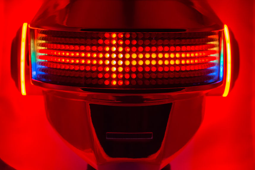
DAFT PUNK
THOMAS HELMET
V2.0
About
As outlined in the Daft Punk Thomas Helmet V1.0 project page, back in the Spring of 2016 I set out to create a Daft Punk helmet (in particular, the chrome Thomas Bangalter helmet) out of a desire for a fun new technical project and attempting to come up with a cool costume for an upcoming party I had been invited to. After completion of the helmet build and showcasing it at Dragon*Con 2017, I realized many shortcomings in both the function and aesthetics of the design and finish. Inspired by the other beautifully crafted Daft Punk helmets that I both witnessed at Dragon*Con 2017 and found during some online research, V2.0 of my Daft Punk Thomas helmet design improved upon my original in many aspects in an attempt at perfection.
In many ways, I became obsessed with project, trying to polish every aspect of the design, both in form an function, both seen and hidden. After attending Dragon*Con 2017, and seeing the near-perfect Daft Punk cosplays donned by the WeAreHumanz duo, I didn't just want an impressive helmet to sport for the following year, I wanted the best. And given my love for tinkering with embedded electronics, I wanted this new design to put forth a spectacular light-show, leveraging modern Arduino-based electronics!
For V2.0, significant changes and improvements included refining the geometric aspects of the helmet relative to V1.0, paying the higher price for a mirror-finish chrome spray treatment, and integrating custom embeded electronics to support a full LED array for the helmet's visor display.
Check out the information below for details regarding the V2.0 helmet features and a media gallery including a demo video. And, if like me, you are an obsessive tinkerer at heart that likes to know all the nitty-gritty details of designing and building something like this, be sure to check out the build journal blog posts linked at the bottom of this page for every exhaustive detail and lesson learned over this history of this build.
Features
3D Sculpted & Designed in CAD Environment
Before physically prototyping and during design iteration, the helmet geometric aesthetics and internal mounting solutions were sculpted and designed in the Autodesk Inventor CAD environment.
Custom Electrical Integration and PCB Design
Leveraging the relative low-cost of custom hobby-grade PCBs, a circular PCB was developed to integrate the microcontroller, breakout-boards, and intermediate circuitry, yielding a cleaner and more integrated design. Additionally, the PCB mounted nicely into the helmet's left ear recess.
SD Card
Support
Utilizing SPI communication with the Teensy 3.2, a microSD card adapter enabled SD card support. This allowed for extended capabilities for future improvements with regard to the helmet's firmware (such as loading more complex animations from the SD card).
3D-Printed Polycarbonate Helmet Body
The helmet-body, ear-caps, and several of the internal mounting solutions were 3D-printed on a SeeMeCNC Rostock Max V2 3D printer using Polymaker's PC-Max polycarbonate filament, yielding a durable long-lasting product.
376 Addressable RGB LEDs
A total of 376 addressable RGB LEDs were used to create both the helmet's visor and ear LED arrays. Adafruit's 24-LED NeoPixel rings were used for each ear LED array. 328 APA106 5mm through-hole LEDs were used to create the helmet's visor LED array, mounted in a laser-cut clear acrylic sheet, and meticulously hand-soldered together.
Bluetooth Support for Smartphone Control
Utilizing Adafruit's Bluefruit LE UART Friend breakout-board, bluetooth support was added to the helmet controller electronics. This enabled connection and helmet animation control using Adafruit's partner smartphone app.
Mirror-Finish Chrome Spray Treatment
After gluing together the 3D-printed helmet body sections and sanding the helmet surface to a pristine smoothness, the outer surface received a SpecraChrome spray-on chrome treatment from the talented folks at Creations N' Chrome.
Modular Visor LED Array Assembly
Utilizing laser-cut acrylic sheets, the visor LED array assembly integrates the visor through-hole LEDs, two 30mm fans for air-circulation and cooling, and the wire-harnesses and connectors for power and logic. The entire assembly is removable via thumb-screws and a series of connectors, allowing the user to easily remove it for improve visibility.
32-Bit Arduino-Based Embedded Controller
PJRC's powerful Teensy 3.2 32-bit microcontroller provided the necessary computing resources to efficiently drive the large number of addressable LEDs, while still having resources available for SD card communication and real-time audio processing.
Microphone Input & Real-Time Audio Processing
Utilizing Adafruit's Electret Microphone Amplifier (MAX9814 with Auto Gain Control), a microphone was added inside the helmet with the Teensy 3.2 providing real-time FFT audio processing, allowing for spectacular audio-responsive LED animations.


